11
RESEARCH OUTCOMES
PHASE 4:- IMPLEMENTING THE TERRAJET
TM
AIR-MOVERS
ONTO A CM
Following Phase 2, Phase 4 focuses on the integration of the
Terrajet
TM
airmover system onto a CM and to perform final
underground concept trials. For the conversion to be successful,
a suitable compressor had to be located, fitted and integrated
onto the CM, as well as install the air-movers correctly to ensure
protection and effective operation.
As reportedpreviously, the airmover systemshowed significant
potential to control the face contaminants, i.e. methane and
dust, but required further trials with a complete CM on-board
system.
The Terrajet air-mover system is a step closer to create and
implement an effective Face Ventilation System that can deal
with airborne dusts and methane gas.
Matla Underground Trials
During the past year, the trials at Matla could not continue due
to failures of the methane and dust communications systems.
It is uncertain when the problems will be solved and when the
underground Terrajet trials will continue.
Sasol Shandoni Trials
A compressor supplier (Integrated Air Solutions) was identified
to locate and import a compact unit suitable to fit onto a
12HM37 CM and have sufficient capacity to supply the four
Terrajets. Integrated Air Solutions imported two separate
compressor units (200 CFM & 300 CFM) for trial purposes.
Following a series of trials in their local workshops, the 200
CFM was opted for as the choice for 12HM37 CM to be used at
Shondoni Mine.
Komatsu has been instrumental in ensuring the success of this
project going forward and have made some modifications onto
a new 12HM37 CM to accommodate the on-board compressor.
Shown below is a sketch that shows the proposed installation
position of the compressor underneath the on-board scrubber.
Figure 1: The compressor is installed underneath the on-
board scrubber
Komatsu made further nodifications on the cutting head of
the new CM to ensure the Terrajets are protected during the
underground trials.
Four Terrajets will be installed onto the CM cutter head, just
behind the rotating drum. The special modification will protect
the Terrajets, with the normal water spray blocks positioned
just behind the cutter drum.
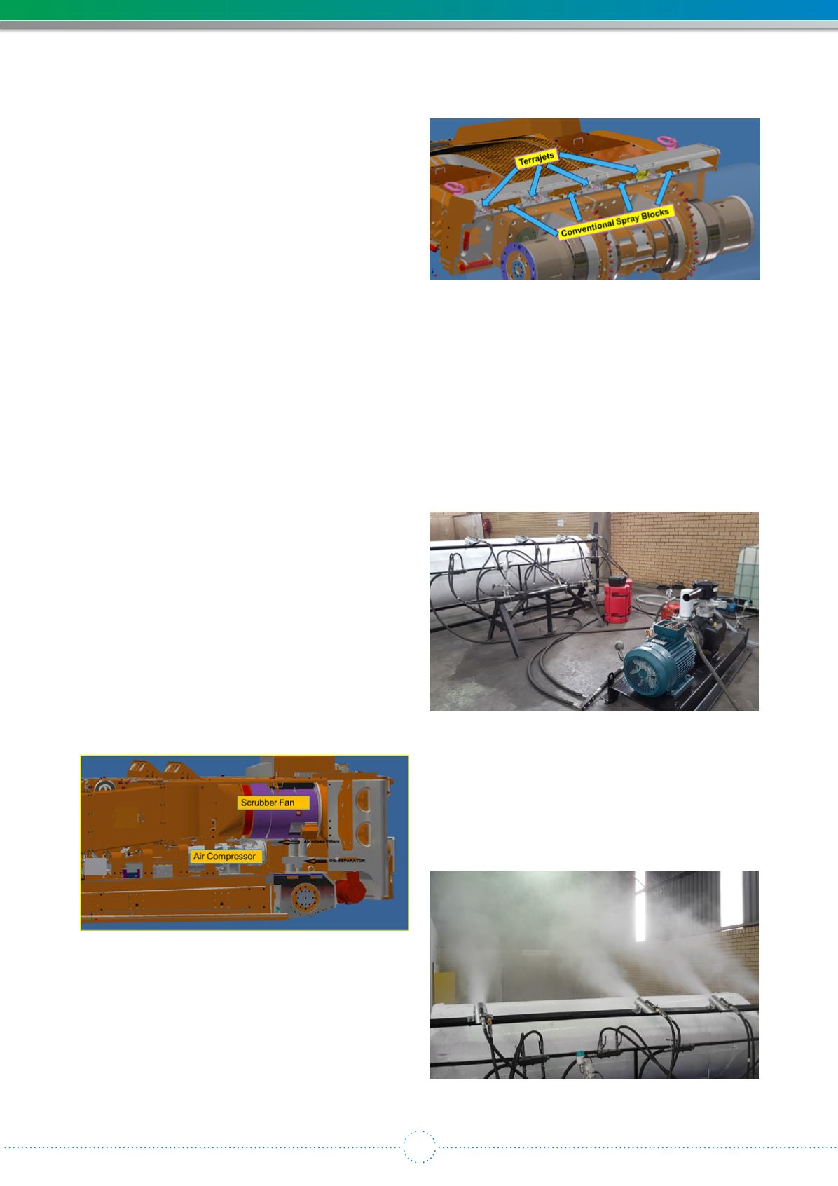
Figure 2 below shows the special modifications made and the
positioning of the Terrajets and the spray blocks.
Figure 2: Positioning of the Terrajets and the spray blocks
under the special protection cover
The Workshop Trails at Integrated Air Solutions to determine
the operating parameters for the four air movers and the 200
CFMAir Compressor were very successful.These parameterswill
be introduced on the CM and the system will be calibrated so
that these parameters are maintained during the underground
trials.
Figure 3 below shows the test setup while the Terrajet system
was evaluated and optimised in terms of Air vs Water usage.
Figure 3: Tests setup for evaluating and optimizing the
Terrajet system for water and air usage
Figure 4 below shows the water mist s created by the four
Terrajet Airmovers with the 200 CFM air compressor. This air/
water quality will be introduced into the face area during the
cutting process, with, it is expected, a significant effect on the
airborne dust generation and the methane gas concentrations.
Figure 4: Air/Water Mist generated through the Terrajets


